The primary/minimal project goal is “draw a triangle on a Radeon R500 via direct memory-mapped hardware register and texture memory accesses”. This means no Mesa, no radeon kernel module, and certainly no OpenGL or Direct3D.
I have worked directly with several other graphics units in the past ( Saturn VDP1, Dreamcast Holly, Voodoo 2). In all of these projects, my strategy is generally:
The rabbit hole for R500 seems significantly deeper, considering this is the first graphics unit I’ve worked with that has programmable vertex and pixel shader engines.
For testing, I currently have this hardware configuration:
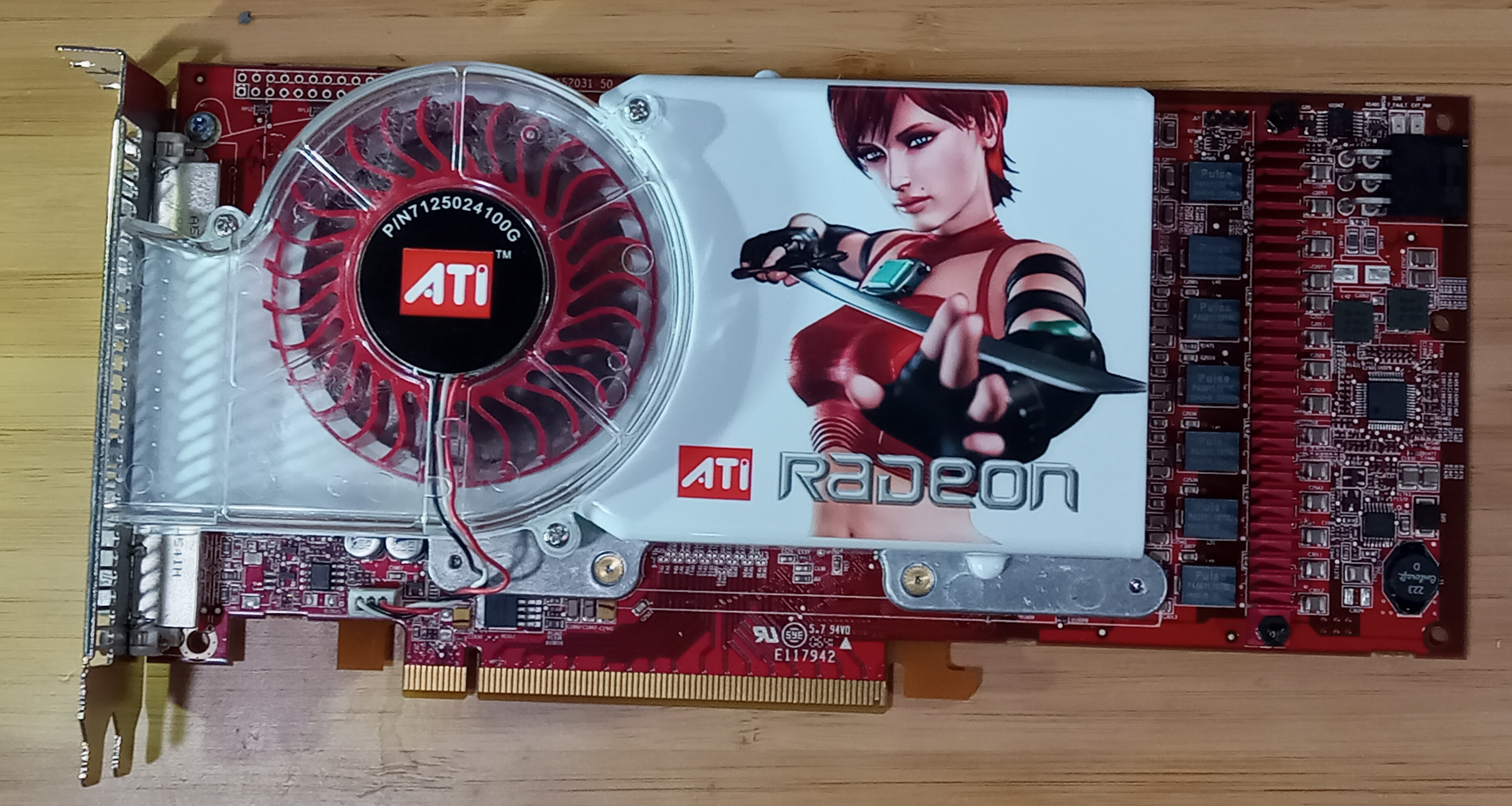
I also have the X1950 XT PCIe shown in the photo, which amazingly has never been used, and prior to the photo was sealed in an antistatic bag from manufacture to now.
While in my other (video game console) projects I typically insist on “bare-metal” development with no operating system or third-party library running on the target hardware, my experience with x86 is much more limited.
While it is something I am interested in doing, I believe creating a zero-dependency “code upload” mechanism for an x86-pc that does not depend on an operating system would severely delay my progress on R500-specific work.
For my initial exploration of R500, I will instead be manipulating the hardware primarily from Linux kernel space. This Linux kernel code does not actually meaningfully depend on Linux APIs beyond calling ioremap to get usable memory mappings for R500 PCI resources (texture/framebuffer memory and registers).
From 01 Oct 2025 to 07 Oct 2025, I achieved the following:
I did not achieve the following:
In general, I note that the R500 documentation is significantly weaker than I hoped, and does not contain enough information to draw a triangle on the R500 from the documentation alone (with no prior knowledge about previous Radeon graphics units).
In addition to the lack of prose, in several cases I’ve noticed both Mesa and Linux reference R500 registers that are not present at all in the documentation.
AtomBIOS physically exists as a section inside the ROM on R500 graphics units. AtomBIOS is notably used for setting PLL/pixel clock frequencies and display resolutions, among several other functions.
The Radeon graphics hardware itself does not execute AtomBIOS code–instead, it is expected that the host (e.g: x86) CPU evaluate the instructions in the AtomBIOS command tables. Generally the outcome of evaluating AtomBIOS code is that several “register write” instructions will be executed, changing the state of the graphics unit.
My original goal in studying AtomBIOS was that I thought I would need it to set up the R500 display controller to a reasonable state (as a prerequisite for drawing 3D graphics). However, after actually experimenting with “disable VGA mode”, I currently believe that I don’t actually need to implement resolution/mode changes, and can proceed without it.
The Linux kernel exclusively communicates with R500 via “PCI bus mastering”. A “ring buffer” is allocated in “GTT” space, which from the graphics unit’s perspective exists in the same address space as framebuffer memory, but is an address that is outside the framebuffer memory that physically exists.
I also observed via debugfs that the GTT apparently involves some sort of sparse page mapping, but I don’t understand how this works from an x86 perspective.
In the absence of an understanding of how to make my own “GTT” address space, I attempted to operate the R500 in “PIO” mode. This has the advantage of being able to simply write to registers via (simple) PCI memory-mapped accesses, but it has the disadvantage that Linux doesn’t use R500 this way, so I have no reference implementation for how PIO mode should be used.
I translated my glDrawArrays notes to equivalent register writes.
This does not work, and I don’t yet understand why. The main issue is that most of the time when I execute that code, Linux appears to “hang” completely, and my “printk” messages are never sent over ssh. On the rare occasion when the “hang” does not occur, a triangle is nevertheless not drawn on the framebuffer.
I have a few ideas for how to proceed:
The latter is perhaps both the most attractive, and the most work. I currently don’t have any understanding of GEM buffers, radeon buffer objects, etc.., so I’d need to study these in more detail.
From 08 Oct 2025 to 14 Oct 2025, I achieved the following:
As implied in the last update, primarily due to my lack of experience with bare-metal x86, I decided it would be a better approach to interact with R500 Command Processor via the radeon kernel module, which provides a partially reasonable interface for this via the DRM_RADEON_CS ioctl.
All DRM_RADEON_ ioctls are mostly or entirely undocumented. Instead, I built debugging symbols for Mesa and other supporting libraries so that I could set breakpoints in GDB to observe what sequences of DRM_RADEON_ ioctls Mesa uses.
From my previous glDrawArrays notes observations, I noticed this strange sequence:
0x0000138a  // type 0 packet, count=0, starting offset = RB3D_COLOROFFSET0
0x00000000  // RB3D_COLOROFFSET0 = 0
0xc0001000  // type 3 packet, count=0, opcode=NOP
0x00000000  // zero (meaningless data)
At first, it seemed Mesa was deliberately setting the colorbuffer write address to (VRAM address) zero, which seemed like a strange choice considering I am debugging an X11/GLX OpenGL application–surely the colorbuffer address would be some non-zero value several megabytes after the beginning of VRAM.
I later attempted to send my own PM4 packet via DRM_RADEON_CS. This initial attempt returned Invalid argument, with the following message in dmesg:
[ 1205.978993] [drm:radeon_cs_packet_next_reloc [radeon]] *ERROR* No packet3 for relocation for packet at 14.
[ 1205.979427] [drm] ib[14]=0x0000138E
[ 1205.979433] [drm] ib[15]=0x00C00640
[ 1205.979437] [drm:r300_packet0_check [radeon]] *ERROR* No reloc for ib[13]=0x4E28
[ 1205.979545] [drm] ib[12]=0x0000138A
[ 1205.979548] [drm] ib[13]=0x00000000
[ 1205.979553] [drm:radeon_cs_ioctl [radeon]] *ERROR* Invalid command stream !
This error message comes from drm/radeon/r300.c.
The meaningless data following the type-3 NOP packet is used by the kernel to index the DRM_RADEON_CS “relocs” array (an array of GEM buffer handles).
It seems perhaps the design goal was to never expose the VRAM address of GEM buffers to userspace (indeed there seems to be no way to retrieve that via any GEM ioctls). This restriction is slightly disappointing, as I would have preferred to be able to send unmodified packet data to the R500.
However, at the moment this does not appear to be a significant issue, as a relatively small number of registers are modified by the Linux kernel’s packet parser prior creating the indirect buffer that is actually sent to the R500 hardware.
There appears to be a lot of memory-to-memory copying in the Linux/Mesa/DRM/GEM/radeon graphics stack:
Eventually, r100_ring_ib_execute is called, which writes the indirect buffer address (now in GPU address space) to the ring.
It would be interesting to experiment with writing a packet buffer directly in GPU/GTT address space (from Linux userspace), with zero copies. This would require an entirely new set of ioctls.
These images were never drawn on-screen. I extracted them from VRAM via /sys/kernel/debug/radeon_vram.
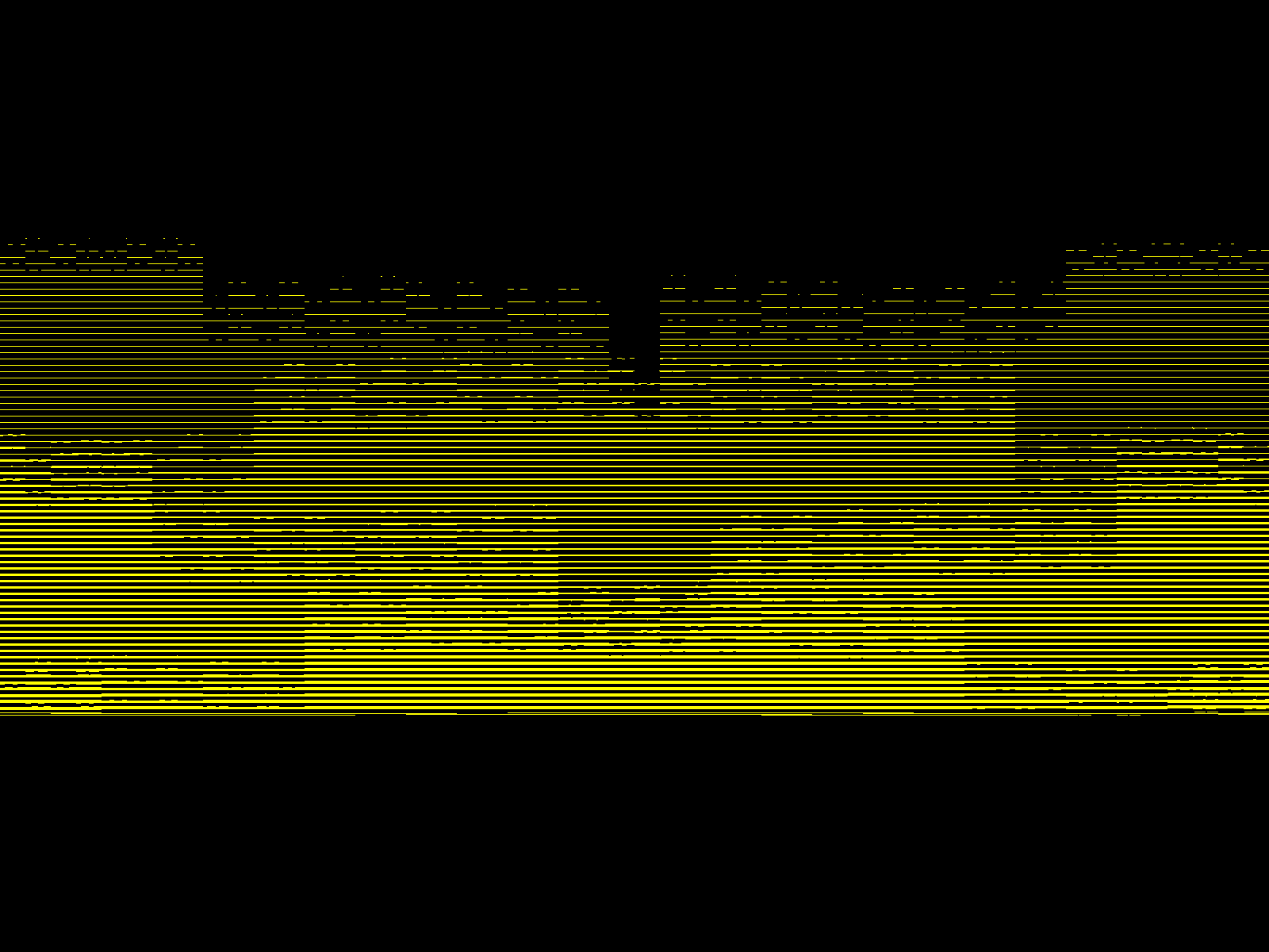
Though I was not aware of it yet, the above image was indeed my triangle, and COLORPITCH0 was merely in “macrotiled” mode. Once I realized this, I produced this image (still in off-screen VRAM):
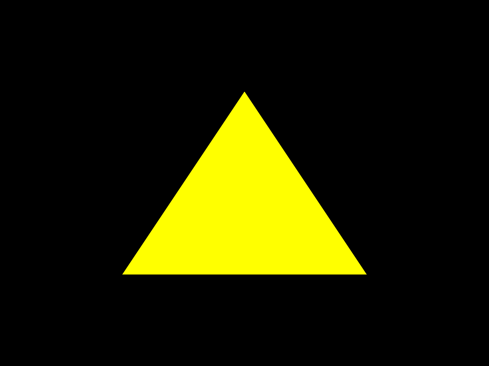
This “single color” demo deliberately uses the very simple vertex and fragment shaders:
instruction[0]:
  0x00f00203  dst: VE_ADD out[0].xyzw
  0x00d10001  src0: input[0].xyzw
  0x01248001  src1: input[0].0000
  0x01248001  src2: input[0].0000
This vertex shader is doing the equivalent of:

The W component comes from VAP_PROG_STREAM_CNTL_EXT__SWIZZLE_SELECT_W_0(5), which swizzles W to a constant 1.0, despite W not being present in the vertex data.
instruction[0]:
  0x00078005  OUT RGBA
  0x08020080  RGB ADDR0=0.0 ADDR1=0.0 ADDR2=0.0
  0x08020080  ALPHA ADDR0=0.0 ADDR1=0.0 ADDR2=0.0
  0x1c9b04d8  RGB_SEL_A=src0.110 RGB_SEL_B=src0.110 TARGET=A
  0x1c810003  ALPHA_OP=OP_MAX ALPHA_SEL_A=src0.0 ALPHA_SEL_B=src0.0 TARGET=A
  0x00000005  RGB_OP=OP_MAX
This fragment shader is doing the equivalent of:

via the src swizzles. I think it is interesting that there are so many options for producing inline constants within the fragment shader.
The “target” fragment shader field also seems interesting. I am excited to write shaders that use multiple output buffers.
These renders were not displayed on-screen, so I looked for ways to correct this.
Perhaps the most obvious method would be to write to the display controller registers (D1GRPH_PRIMARY_SURFACE_ADDRESS) via RADEON_DRM_CS. However, this does not work due to the command parser anti-fun implemented in r300_packet0_check: any register not present in that case statement is considered invalid, and the packet buffer is not submitted.
I attempted to do this the “right way” via the DRM/KMS/GBM APIs. I then learned that this does not behave correctly on my R500 because demos that wait for the flag returned by DRM_IOCTL_MODE_PAGE_FLIP hang forever.
I noticed this earlier on Xorg/GLX as well, as I have been using the vblank_mode=0 environment variable to avoid hanging forever in glXSwapBuffers. This appears to be a Linux kernel bug, but I didn’t investigate this further.
I noticed in /sys/kernel/debug/radeon_vram_mm that the Linux console is only using a single framebuffer (and does not double-buffer).
This is fortunate, because this means I can simply mmap the register address space and write D1GRPH_PRIMARY_SURFACE_ADDRESS myself without worrying about the Linux console overwriting my change. I observed the 0x813000 value from /sys/kernel/debug/radeon_vram_mm–there appears to be no other way to get the vram address of a GEM buffer.
This is “good enough” for now, though at some point I’ll want to learn how to do proper vblank-synchronized double buffering.
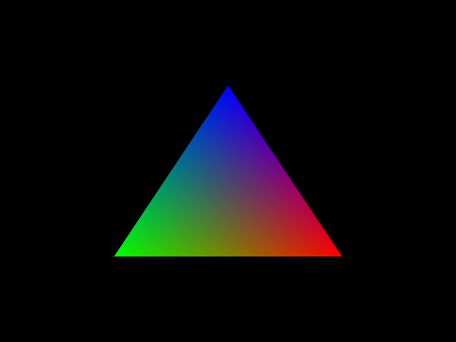
I felt the next logical step was to learn how attributes and constants are passed through the shader pipeline, so I then created a demo that produced this image (this time also displayed on-screen):
instruction[0]:
  0x00702203  dst: VE_ADD out[1].xyz_
  0x01d10021  src0: input[1].xyz_
  0x01248021  src1: input[1].0000
  0x01248021  src2: input[1].0000
instruction[1]:
  0x00f00203  dst: VE_ADD out[0].xyzw
  0x01510001  src0: input[0].xyz1
  0x01248001  src1: input[0].0000
  0x01248001  src2: input[0].0000
This vertex shader is doing the equivalent of

The extra vertex input is fed to the vertex shader via changes to VAP_PROG_STREAM_CNTL_0, VAP_PROG_STREAM_CNTL_EXT_0. Based on my currently limited understanding, it seems that arranging the vertex data like this:

Is easier to deal with in VAP_PROG_STREAM_CNTL than:

instruction[0]:
  0x00078005  OUT RGBA
  0x08020000  RGB ADDR0=temp[0] ADDR1=0.0 ADDR2=0.0
  0x08020080  ALPHA ADDR0=0.0 ADDR1=0.0 ADDR2=0.0
  0x1c440220  RGB_SEL_A=src0.rgb RGB_SEL_B=src0.rgb TARGET=A
  0x1cc18003  ALPHA_OP=OP_MAX ALPHA_SEL_A=src0.1 ALPHA_SEL_B=src0.1 TARGET=A
  0x00000005  RGB_OP=OP_MAX
This fragment shader is doing the equivalent of:

The temp input appears to be written by VAP_OUT_VTX_FMT_0__VTX_COLOR_0_PRESENT and read due to the changes to RS_COUNT and RS_INST_0.
From 15 Oct 2025 to 21 Oct 2025, I achieved the following (roughly in chronological order):
While attempting refactor one of my R500 demos to send fewer registers per DRM_RADEON_CS ioctl, I found that there is a “state tracker” within the drm/radeon/r100. For example, even if you don’t use or depend on a Z-buffer, DRM_RADEON_CS will still reject your packet buffer depending on its own (imagined) concept of what the GPU state is. For example:
[ 1614.729278] [drm:r100_cs_track_check [radeon]] *ERROR* [drm] No buffer for z buffer !
[ 1614.729626] [drm:radeon_cs_ioctl [radeon]] *ERROR* Invalid command stream !
This happens because track->z_enabled is initially true at the start of a DRM_RADEON_CS ioctl, and does not become false unless the packet buffer contains a write to ZB_CNTL.
This seems a bit heavy-handed. Even if the model were “multiple applications may be using the GPU, so a single application can’t depend on previously-set register state”, it would still be better if the kernel didn’t try to enforce this by restricting permissible content of a packet buffer.
Mesa uses a “point” 3D primitive to implement glClear on R500. It does this by first uploading this vertex shader:
![]()
This shader does nothing to the input other than copy it to the output, where out[0] is the position vector, and out[1] is sent to the fragment shader as a “texture coordinate”. That fragment shader, in turn, does not use the texture coordinate:
![]()
In my “clear” implementation, I instead set PVS_BYPASS, which “bypasses” the vertex shader completely, sending the vertices directly to the rasterizer. This is convenient because it obviates the need to upload/change vertex shaders just to clear the color and Z -buffers.
With a working colorbuffer clear, I wrote the single_color_clear_translate.c demo to translate my triangle position coordinates in a loop that waits for DRM_RADEON_GEM_WAIT_IDLE between each frame. This attempt produced the following images:
This was intended to be a smooth animation, yet it is not. It also seems several frames are never being displayed–the translation step is much smaller than what is shown in the video.
This, interestingly, is exactly identical to how OpenGL/GLX applications behave on R500 with vblank_mode=0.
I read the R500 display controller register reference guide again. It appears to suggest the D1CRTC_UPDATE_INSTANTLY bit, when unset, might cause changes to D1GRPH_PRIMARY_SURFACE_ADDRESS to be delayed in hardware until the next vertical blanking interval begins.
This can be combined with polling D1GRPH_SURFACE_UPDATE_PENDING to later determine when the vblank-synchronized frame change actually occured.
This is precisely what I implemented in single_color_clear_translate_vblank.c:
This is much closer to what I intended. The D1GRPH_SURFACE_UPDATE_PENDING part is certainly working as I expected. Setting/unsetting D1CRTC_UPDATE_INSTANTLY appears to have no effect on D1GRPH_PRIMARY_SURFACE_ADDRESS behavior, so I feel my understanding of R500 double-buffering is still incomplete.
I am amazed and delighted how simple multiple-texture sampling is on R500.
As a counter-example, while Sega Dreamcast does have a fairly capable fixed-function blending unit, to use the blending unit with multiple-texture sampled polygons one needs to render the polygon multiple times (at least once per texture) to an accumulation buffer. Blending is then performed between the currently-sampled texture and the previously-accumulated result, and the blend result is written to the accumulation buffer. From a vertex transformation perspective, it can be inconvenient/inefficient to be required to buffer entire triangle strips so that they can be submitted more than once per frame without duplicating the clip/transform computations.
This is the fragment shader for texture_dual.c (disassembly of code originally generated by Mesa):

This pre-subtract multiply-add is an algebraic rearrangement of this GLSL code:

Which produces this image:
Being able to manipulate the texture samples as fragment shader unit temporaries rather than as a sequence of accumulation buffer operations has me feeling excited to do more with this.
I’ve never worked with traditional Z-buffers before–Sega Saturn uses painter’s algorithm exclusively, and Sega Dreamcast uses a “depth accumulation buffer” that isn’t directly readable/writable.
It is slightly obvious in retrospect, but it took me several minutes to realize that a “depth clear” can be implemented by covering the entire screen with a “point” primitive with the desired initial depth while ZFUNC set to ALWAYS.
With working double-buffering, Z-buffering, and the ability to clear each of these every frame, I felt I was finally ready to draw something “3D”.
I thought it would be fun to first start with a cube that is transformed in “software” on the x86 CPU (not using a vertex shader). This sequence of videos shows my progression on implementing this:
I then decided it would be fun to hand-write a “3D rotation” vertex shader from scratch. I first implemented the rotation in GLSL:

Because this shader program depends on being able to calculate sin and cos, this meant I immediately needed to understand how to use the ME_SIN and ME_COS operations.
The R500 vertex shader ME unit clamps sin/cos operands to the range
 , as in:

“Remapping” floating point values from  to
to  is not
obvious. I was not previously aware of this transformation:
is not
obvious. I was not previously aware of this transformation:

Or, expressed as R500 vertex shader assembly:

Having verified that the GLSL version works as expected in OpenGL, and knowing how to use the R500 vertex shader sin/cos operations, then I translated the GLSL to R500 vertex shader assembly, as:

However, when I first executed the vertex shader cube rotation demo, I found it did not work as expected:
After hours of debugging, I eventually found the issue was in this instruction:

R5xx_Acceleration_v1.5.pdf briefly mentions this on pages 98 and 99:
The PVS_DST_MACRO_INST bit was meant to be used for MACROS such as a vector-matrix multiply, but currently is only set for the following cases:
A VE_MULTIPLY_ADD or VE_MULTIPLYX2_ADD instruction with all 3 source operands using unique PVS_REG_TEMPORARY vector addresses. Since R300 only has two read ports on the temporary memory, this special case of these instructions is broken up (by the HW) into 2 operations.
I read this paragraph much earlier, but I didn’t fully understand it until now. Indeed, this multiply-add has three unique temp addresses, and must be encoded as a “macro” instruction.
I fixed this in my vertex shader assembler by counting the number of unique temp addresses referenced by each instruction, promoting VE_MULTIPLY_ADD to PVS_MACRO_OP_2CLK_MADD if more than two unique temp addresses are referenced.
With this change, reassembling the same vertex shader source code now produces a correct vertex shader cube rotation:
My “cube rotation” vertex shader, cube_rotate.vs.asm is 15 instructions.
Mesa’s R500 vertex shader compiler generated a 27-instruction vertex shader from semantically equivalent GLSL code. Disassembly:

I was not particularly trying to write concise code, but I find this difference in instruction count to be surprising. In general it seems Mesa’s R500 vertex shader compiler failed to vectorize several operations, and does significantly more scalar multiplies and scalar multiply-adds than my implementation.
Ignoring algorithmic improvements (such as lifting the sin/cos calculation to x86 code and instead sending a 4x4 matrix to the vertex shader), there is still more opportunity for optimization beyond my 15-instruction implementation.
Particularly, the vertex shader unit has a “dual math” instruction mode, where “vector engine” (VE_) and “math engine” (ME_) operations can be executed simultaneously in the same instruction. cube_rotate.vs.asm would indeed benefit from such an optimization–most of the ME_SIN and ME_COS instructions could be interleaved with the VE_MUL and VE_MAD operations that follow (at significant expense to human-readability).
I am curious to see more examples of the difference between Mesa’s R500 vertex shader compiler output and my own vertex shader assembly.
Compared to the R500 vertex shader instructions, the R500 fragment shader instructions are significantly more featureful. This makes inventing a syntax that can fully express the range of operations that a R500 fragment shader instruction can do more complex.
A significant difference is where R500 vertex shaders have a single tier of operand argument decoding, as in:
While R500 fragment shaders have multiple tiers of operand argument decoding, as in:
I’ve written several nice assemblers for other architectures in the past, but I’ve never seen any instruction set as expressive as R500 fragment shaders.
I attempted to directly represent this “multiple tiers of operand argument decoding” in my fragment shader ALU instructions syntax.
These instructions are also vector instructions: a total of 24 floating point input operands and 8 floating results could be evaluated per instruction.
With this abundance of expressiveness and a relatively high skill ceiling, I’m amazed R500 fragment shader assembly isn’t more popular in programming competitions, general everyday conversation, etc...
There were two “I spent a lot of time debugging this” issues I encountered with my fragment shader assembler.
The first was in this code I wrote to draw a fragment shaded circle, as in:

However, in an earlier version of my fragment shader assembler, I produced this image instead:

In this handwritten fragment shader code:

R5xx_Acceleration_v1.5.pdf says briefly on page 241:
Specifies whether to insert a NOP instruction after this. This would get specified in order to meet dependency requirements for the pre-subtract inputs, and dependency requirements for src0 of an MDH/MDV instruction.
The issue is the pre-subtract input for the MAD |srcp.a| src0.1 -src2.a instruction depends on the write to temp[0].a from the immediately preceding RCP src0.a instruction–a pipeline hazard.
To fix this, I added support for generating the NOP bit in my fragment shader assembler.
While trying to produce this image:

My fragment shader code instead produced this image:
The issue was simply that in the chaos of all of the other features I was implementing for my fragment shader assembler, I forgot to emit the ADDRD bits.
This meant that while fragment shader code that exclusively uses zero-address destinations, such as shadertoy_circle.fs.asm, appeared to work completely correctly, I encountered this bug as soon as I started using non-zero addresses such as temp[1] in my fragment shader code.
Prior to Direct3D 10, Microsoft previously defined a specification for both vertex shader assembly and fragment shader assembly.
The Direct3D “asm” name is slightly deceptive, however, as the vs_3_0 and ps_3_0 instruction syntax does not map 1-to-1 with any hardware that exists.
It would perhaps be more accurate to think of Direct3D’s “asm” language and compiler as more analogous to a shader BASIC than as a true assembly language on the same level as “6502 assembly”, “Z80 assembly” and similar.
In contrast, my R500 assembly syntaxes are deliberately/explicitly mapped 1-to-1 with R500 instructions.
The R500 fragment shader code that I handwrote for this is:

The float constants are interesting–they are decoded almost identically to the 8-bit (1.4.3) (bias 7) format shown on Wikipedia, except:
The exponent/mantissa table that shows example 7-bit float values on page 106 of R5xx_Acceleration_v1.5.pdf is incorrect.
From 21 Oct 2025 to 26 Oct 2025, I achieved the following (roughly in chronological order):
After talking about it in-person, I decided to try to golf my original 15-instruction cube_rotate.vs.asm vertex shader.
The first opportunity for optimization is in the first two instructions of:

The VE_ADD (being used here as a “MOV” instruction) is needed because there is only a single 128-bit read port into const memory, so a multiply-add like this is illegal:

I observed that because I never need to reference the last two constants in the same instruction that references the first two constants, if I rearrange the ordering of the constants to:

I can then rewrite the multiply-add instructions as:

I spent an entire day rewriting large portions of the vertex shader assembler to add support for “dual math” instructions.
The original cube_rotate.vs.asm contains this sequence of ME_SIN/ME_COS instructions:

The temp[3].x and temp[3].y results are needed immediately, but temp[3].z and temp[3].w are not needed until after the first pair of VE_MUL/VE_MAD operations.
The dual math instruction mode replaces the 3rd VE_ instruction operand with any ME_ operation, so it is only usable with 2-operand VE_ instructions like VE_MUL.
The dual math encoding also has several restrictions (it only has 1/4th the control word bits compared to a normal ME_ instruction). A notable restriction is that it must write to alt_temp.
Unlike the fancy things that can be done with fragment shader operands/sources/swizzles, a single vertex shader operand can also only read from a single 128-bit register, so this means to be able to continue to access temp[3].zw as a vector, both z and w must now be stored in alt_temp, even if only one of them was written by a “dual math” instruction.
The change (and my newly-implemented dual math syntax) is:

Where the dual math instruction:

Is encoded by the assembler as single instruction and is executed by the vertex shader unit in a single clock cycle.
The final cube_rotate_optimize.vs.asm was reduced from 15 instructions to 13 instructions (compared to Mesa’s R500 vertex shader compiler’s 27 instructions).
From 27 Oct 2025 to 29 Oct 2025, I achieved the following (roughly in chronological order):
Though I produced a “properly” Z-buffered 3D cube demo previously, I felt I did not fully understand the relationship between Z coordinates, W coordinates, viewport transformations, and the actual values that are written the the Z-buffer. At some point, I’d like to write fragment shaders that sample the Z-buffer, so I feel I need to understand this more rigorously.
For comparison, Sega Dreamcast stores 32-bit floating-point values in the “depth accumulation buffer”. This effectively means that any Z coordinates can be stored in the depth accumulation buffer without scaling or range remapping. I’ve made several moderately fancy Dreamcast demos in that happily store arbitrary “view space” Z values in the depth accumulation buffer without any visible depth aliasing/artifacts.
In contrast, the Radeon R500 does not have a 32-bit floating point Z-buffer format. Instead, R500 supports ( R5xx_Acceleration_v1.5.pdf, page 283, ZB_FORMAT):
The third option, with the most bits, clearly ought to give the most precision–with the caveat that the Z values that are written to the Z-buffer should be scaled to be uniformly distributed across the range of 24-bit integers.
I performed several tests with variations of zbuffer_test.c. The general strategy was:
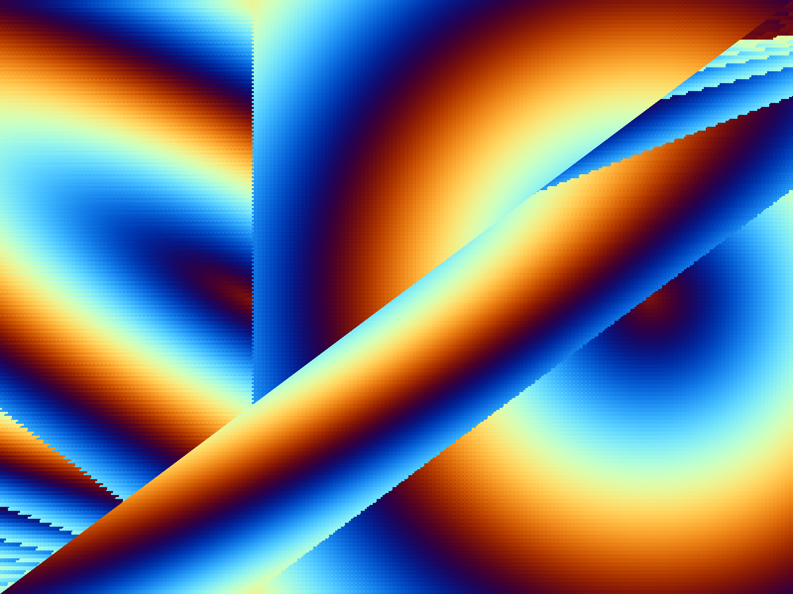
The first scene I chose was of a tilted plane that is non-coplanar with the view space XY plane, as in:
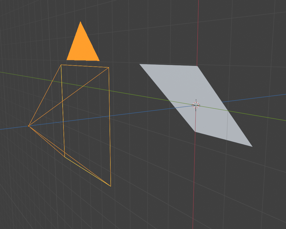
Where the grey plane is the object that is to be rendered, the yellow lines represent a “camera” from which the plane is to be viewed, and the blue line represents the view/clip-space Z axis.
To view the content of the Z buffer, I wrote a simple script to convert the 24-bit integer Z-buffer to 16-bit PGM, so that it can be easily viewed in an image editor. This tool also shows the minimum and maximum values found in the Z-buffer, intended to help verify that the entire numeric range of the Z-buffer is being used.
While I expected to see the (orthographic, directly facing the camera) plane drawn on the Z-buffer as a smooth gradient such as:

Several of my tests displayed numeric aliasing, overflows, underflows, etc..:

Of particular interest to me was to verify the behavior of the DX_CLIP_SPACE_DEF bit ( R5xx_Acceleration_v1.5.pdf, page 255–this is also the only place in the entire manual where “non-user” clip planes are even defined), and to understand the order of pipeline operations.
I played with moving the plane around, to observe clipping behavior (here the lower half of the scene was clipped due to intersecting the Z=+1.0 clip plane):

Thinking at this point that I nearly understood most of the pieces, I then re-enabled XY perspective division:

The above image was not quite what I wanted: I noticed the range of the Z buffer values were roughly between 0 and 8388607, but what I really wanted was 0 to 16777215. Adjusting scale again produced this Z-buffer:

Up to this point, I was using ZFUNC=GREATER with a Z-buffer cleared with an initial depth of zero, where all Z values are negative numbers.
I decided it might be more intuitive to use a Z-buffer that is cleared with an initial depth of one, using ZFUNC=LESS instead where all Z values are positive numbers.
With these adjustments, I captured a Z-buffer from the earlier cube demo:

This was still not quite “correct”, because the minimum depth of the cube is being drawn as ~2763306 (~0.16), but I expected something closer to zero.
Adjusting my range/scale arithmetic again produced this image:

The minimum Z value now appears to be closer to zero, but the “back” faces of the cube (and maximum Z values) are not visible. Without changing any scale/range constants, inverting ZFUNC and using a zero-initialized Z-buffer produced this image of the back faces of the cube:

Indeed, the maximum Z value is close to ~16777215 (~1.0), as intended. I feel at this point I have a better intuition for using integer Z-buffers. The pipeline (and relevant registers) appears to be something like this:
Prior to these experiments, I was not aware SU_DEPTH_SCALE is the thing directly responsible for scaling floating point Z values to the integer Z values stored in the depth buffer.
In general, the hardware perspective divide, viewport transform, clipping, and setup units are absolutely fascinating.
Despite making many 3D demos in the past, I feel that every time I want to “draw something 3D” on a new platform, I need to re-relearn 3D/perspective transformations, (perhaps because I never truly learned anything).
In many OpenGL articles/tutorials/books the standard formula for explaining perspective projection appears to be:
It is sufficient to instead rationalize/implement “perspective” as:
Perspective is the division of X and Y coordinates by Z, where the coordinate
is the view origin (and the center of the screen/projection).
Defining perspective this way also works for OpenGL, with some slight adjustment, notably to deal with OpenGL’s definition of “normalized device coordinates”.
I note that (unlike Dreamcast) one can’t actually divide by Z on R500 (nor OpenGL), both because the VTE doesn’t support this, and because the texture unit doesn’t support this. Of course, I tried it anyway:
Instead, in both cases, the R500 uses the W coordinate for division. This turns out to be very convenient, because it means that that the “field of view”/perspective scale (W) and the Z-buffer/depth test scale (Z) can be adjusted independently.
Here are several examples of improperly scaled Z values, which are being clipped by the setup unit:
 was a good idea)
From 30 Oct 2025 to 31 Oct 2025, I achieved the following (non-chronological):
Despite being a “simple” lighting demo, a surprising number of things need to happen simultaneously before it becomes possible.
Where vertex shaders from previous demos were passed at most a single scalar variable for animation/timing, the vertex shader in this demo uses 10 vectors as input:
Additionally, where previous demos passed at most a single vector from the vertex shader to the fragment shader (vertex color or texture coordinates), this demo passes 5 vectors from the vertex shader to the fragment shader, all of which are used by the lighting calculation:
Prior to today, I did not know about this transformation/equivalence:

While the R500 fragment shader alpha unit does not have a POW operation, it does have EX2 and LN2 operations.
For example, one could implement  in R500 fragment shader assembly
as:
in R500 fragment shader assembly
as:

This “arbitrary exponents with arbitrary bases” pattern is used in the lighting demo fragment shader as part of the “specular intensity” calculation.
This fragment shader unit feature is very cool, because a software implementation of a generalized floating-point pow function is extremely computationally expensive otherwise.
From 1 Nov 2025 to 11 Nov 2025, I achieved the following:
I felt “Shader Art Coding Introduction” would be fun to reimplement as R500 fragment shader assembly: it produces an interesting visual effect, despite not being particularly complicated.
In general when writing assembly programs, I use a few techniques to improve my productivity and accuracy, prior to writing any actual assembly:
In particular, my goal in this step is to make each line of GLSL roughly equal to one fragment shader instruction. I started by rewriting all of the function calls the original code made as:

Defining replacements for GLSL’s built-in functions is not a good practice for writing GLSL code in general. However, the goal in this specific situation is to give myself line-by-line hints on the R500 fragment shader assembly that I’ll eventually need to write.
I then rewrote the main function in a similar “one line of GLSL per R500 instruction” style as:

I also decided the multiplication by 0.125, where it normally would have required a separate multiply-add instruction, was a perfect excuse to implement assembler support for the “OMOD” R500 fragment shader feature/syntax that I previously implemented in my fragment shader disassembler.
Still prior to writing any fragment shader assembly, I then decided where I would store each GLSL variable in fragment shader temporary/constant memory:

I intentionally stored scalar values in the alpha component of each vector. Given my current fragment shader assembler syntax, this allows for slightly more improved human-readability. For example, doing a scalar multiply-add with the alpha unit looks like this:

If the d variable were instead stored in the blue component, the code would be slightly uglier, as in:

Because the GLSL code was transformed to very closely match the fragment shader assembly, this also makes it easy to test the fragment shader output when only a fraction of the complete program is translated (e.g: by commenting out chunks of the GLSL code to match the current state of the in-progress fragment shader assembly translation).
The visual appearance of a half-translated varient of this fragment shader is not intuitive, so this technique greatly improves debuggability. I made at least at least two mistakes while translating that were not difficult to debug at a per-instruction level by comparing the equivalent GLSL code’s visuals.
Though the R500 does support it, my fragment shader assembler does not currently implement support for loops (or any other type of flow control).
R500 fragment shader flow control is also relatively expensive compared to “loop unrolling”, particularly in this case where the loop body is only 32 instructions, and there are only 4 total iterations of the loop body.
For this reason, I decided I wanted a concise and generalized way to “repeat” chunks of source code in my fragment shader assembler, without actually duplicating the text.
To do this, I implemented an “#include” feature in my fragment shader assembler. This is conceptually similar to how #include works in the C programming language, though my implementation simply feeds tokens from the included file directly from the (nested) lexer to the parser, rather than the much more complex procedure used by the C preprocessor.
With this new feature, the translation of the GLSL loop is very simple:

The full implementation is committed as shadertoy_palette_fractal.fs.asm and shadertoy_palette_fractal_loop_inner.fs.asm.
ATI documentation mentioned the existence of a “Render to Vertex Buffer” feature.
The general idea/revelation is:
The state manipulated by the pixel shader is double-buffered, where each iteration of the fragment shader uses alternating “read” and “write” buffers, as in:
On the subsequent iteration of the same computation, state “b” would be read and state “a” would be written.
For all prior fragment shader demos, I used the 32-bit C4_8 surface format:

Where 8-bit unsigned integer representations of blue, green, red, and alpha could be stored in C0, C1, C2, and C3 respectively (or any other arbitrary color component ordering).
R500 also supports a 128-bit C4_32_FP surface format:

Where each component contains a 32-bit floating point value. Compared to 8-bit integers, this increase in precision makes the format more useful for generalized computation.
R500 conveniently also has an equivalent 128-bit per texel, 32-bit floating point per component, 4-component texture format.
I decided a minimal but still “mildly interesting” particle system would need at least the following state:

age is used to both “reset” the particle after some time (allowing the simulation to repeat indefinitely) and to give the particles non-uniform reset timing. random is used to further make the behavior of each particle less uniform. At the start of the particle simulation, all values are randomly initialized.
This data model requires 8 components in total, which is more than the 4 components provided by both the pixel shader output surface format as well as the texture sampler texel format. However:
Following this model, it makes sense to break up the data structure like this:

Where each fragment samples from two separate texture buffers, and has two separate render targets as output:
I decided to draw particles using the R500’s “quad list” primitive. In a non-fragment-shader-computed version of my particle simulation demo, I sent the particle position as a vertex shader constant, as in:

The vertex shader is then able to calculate the quad vertex positions using a vertex shader program that is equivalent to this GLSL code:

This works reasonably well for small particle system demos where particle position is calculated on the CPU. However, the goal is to compute (much larger) particle system positions via the pixel shader, and it would be highly preferred that the particle system state never leaves R500 VRAM. In the latter case, the “combine quad position coordinates with particle position coordinates via vertex shader constants” approach does not work for several reasons:
The only remaining option is to store particle position coordinates as a vertex buffer. However, because I am drawing quads, despite the R500 vertex fetcher’s generous flexibility, the particle state buffer can’t be used directly by the vertex shader because it operates on individual vertices, and not on entire primitives.
For example, if a particle is at position (4.0, 5.0, 6.0), the data that needs to be sent to the vertex shader should be:

Or, expressed as a texture, the desired transformation is:

While the R500 pixel shader unit can’t itself perform this transformation directly, the transformation can indeed be achieved by “scaling” the particle state via the R500 setup engine and fragment interpolators using point texture sampling.
Doing this via point texture sampling is absolutely critical, because a linear interpolation between the state of two adjacent-in-memory particles is a completely meaningless operation in this context.
This is implemented in _copy_to_vertexbuffer as simply “rendering” the particle positions into a viewport that is 4x wider than the width of the original particle state texture.
All buffers in the following diagram are entirely stored in R500 texture memory, and are never transferred to x86 RAM.
The full rendering pipeline implementation is committed as particle_oriented_animated_quad_vbuf_pixel_shader.cpp.
The full particle simulation pixel shader implementation is committed as particle_physics.fs.asm.
Speed comparison of my test system’s Pentium 4 CPU and R500 pixel shader simulating the same particle system (131,072 particles):
A more colorful variant of the same particle system demo (65,536 particles):
It is exciting for me to realize that this “perform generalized computations via R500 pixel shaders” technique has myriad other possible applications.